
Introduction
Bevel gear cutting is the machining process that forms angled or curved teeth onto the conical surface of a gear blank. This lets two shafts whose axes intersect, most commonly at 90 degrees, transmit rotational power to one another.
For plant maintenance managers, reliability engineers, and machine shop buyers in power generation and heavy industry, this process matters more than the terminology suggests. Whether a bevel gearbox runs quiet and cool for a decade or fails within months often traces back to how well the original teeth were cut.
The term gets tossed around loosely in maintenance conversations and is frequently confused with standard spur or helical gear cutting. It isn't the same process, and treating it like it is causes real problems: noise, heat, premature wear, and unplanned downtime.
This article breaks down how bevel gear cutting works, what factors determine quality, where it's applied in industrial settings, and when it might not be the right call at all.
Key Takeaways
- Bevel gear cutting forms teeth on a conical blank so shafts that meet—usually at 90°—can transmit power
- Face milling and face hobbing are the two dominant industrial cutting methods, each producing different tooth geometry
- Tooth count, module, bevel angle, and cutter material drive noise, load capacity, and service life
- Dimensionally correct gears still need tooth-contact checks before they are production-ready
- Knowing when to re-cut versus replace a worn gear prevents unnecessary downtime and cost
What Is Bevel Gear Cutting?
Bevel gear cutting is the process of machining angled or curved teeth onto the conical face of a gear blank so it meshes correctly with a mating bevel gear on an intersecting shaft. The result is a conical gear with the correct pitch angle, module, and tooth profile—one that transmits torque smoothly and quietly between shafts that aren't parallel.
How Bevel Gears Differ from Spur and Helical Gears
Spur and helical gears are cylindrical, with a constant tooth profile running the full length of the tooth. Bevel gear teeth taper instead. Tooth thickness and depth change from the outer end (heel) to the inner end (toe), scaling in proportion to diameter along that conical surface. That taper is why bevel gears need multi-axis or specialized cutting methods rather than the straightforward hobbing used on cylindrical gears.
The Four Inputs Used to Calculate a Bevel Gear
Sizing and cutting a bevel gear comes down to four core inputs:
- Tooth count for both the pinion and the mating gear
- Module, measured at the larger (outer) end of the tooth
- Bevel or pitch angle, which combines with its mating gear's angle to equal the shaft angle (90 degrees total for a right-angle set)
- Face width, the length of the tooth along the cone
A common misconception is that every 90-degree bevel set splits evenly into two 45-degree pitch angles. That only happens with equal tooth counts, known as a miter gear pair. Once the tooth counts differ, the two pitch angles still sum to 90 degrees, but they split unevenly based on the ratio between the gears, according to KHK's gear dimension calculation reference.
Finding the Right Gear Ratio
There's no universal "ideal" bevel gear ratio—it depends on what the application needs:
- 1:1 (miter gears) redirect a shaft's power without changing speed or torque
- Unequal ratios are chosen when the application also needs a speed or torque conversion alongside the direction change
The right ratio gets calculated against the specific load, speed, and space constraints of the equipment, not pulled from a standard chart.
Straight, Spiral, and Zerol Tooth Lines
Bevel gears come in three tooth-line styles, and the choice determines which cutting method applies:
- Straight teeth point directly toward the cone's apex
- Spiral teeth curve across the face for smoother, quieter engagement
- Zerol teeth follow a curved path similar to spiral but with a net spiral angle of zero at the midpoint

Straight bevel gears are typically produced with dedicated systems built for that geometry. Spiral and Zerol forms are cut using face milling or face hobbing, both covered in detail below.
Why Bevel Gear Cutting Is Used in Power Plants and Heavy Industry
Anywhere power needs to move between two shafts that intersect rather than run parallel, bevel gearing is usually the answer. Right-angle drives inside pumps, mixers, conveyors, and auxiliary gearboxes across power plants and heavy industrial facilities depend on it.
Continuous-duty service leaves little margin for error. A right-angle drive running 24/7 in a power plant can't tolerate excessive noise, marginal load capacity, or poor tooth contact. Quiet running, full load capacity, and proper tooth contact only come from bevel gear cutting and finishing done correctly the first time.
What Goes Wrong Without Precision
Improperly cut or worn bevel teeth cause poor tooth contact, pitting, chipping, and excessive backlash. Left unaddressed, all of that leads to premature gearbox failure. And gearbox failure is expensive.
An ABB survey of over 3,200 plant-maintenance decision-makers across energy, oil and gas, and utilities found that more than two-thirds of industrial facilities experience unplanned outages at least monthly, with a typical cost near $125,000 per hour. That figure covers unplanned industrial downtime broadly—not gearbox failures alone—but it shows why a single hour matters.
Where This Fits in the Equipment Lifecycle
Bevel gear cutting happens at two distinct points:
- Original equipment manufacturing, when the gearbox is first built
- Maintenance, remanufacturing, or emergency repair, when inspection or failure reveals a scored, cracked, or worn-beyond-tolerance gear or pinion
The second scenario is where things get urgent. When a bevel gearbox fails unexpectedly and takes a power plant offline, there's no time for an 8-to-10-month new-unit lead time. This is where specialists like Houston Pump & Gear step in. Their 24/7 emergency response coordinates pickup and replacement gear work so rotating equipment gets back in service fast.
That capability isn't theoretical. In 2014, a power plant operator's Lufkin S2212C gearbox failed, forcing an emergency shutdown. Houston Pump & Gear sent a truck the same day, picked up the unit, and returned the plant to operation 72 hours later. That customer has since had more than 15 additional units serviced by the company.

How Bevel Gear Cutting Works
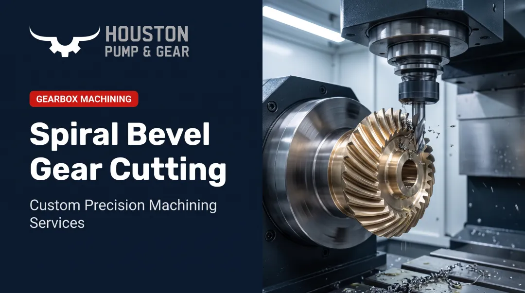
The process starts with a gear blank machined to the correct conical dimensions. Teeth are then cut into that conical surface using either single-indexing (face milling) or continuous-indexing (face hobbing) methods, followed by heat treatment and finishing.
Core inputs include:
- A forged or cast gear blank
- CAD-derived settings for module, pressure angle, and bevel angle
- A cutter or blade (historically high-speed steel; now more often coated carbide)
CNC controls manage cutter tilt, indexing, feed rate, and blade geometry. Teams often run tooth contact analysis (TCA) software first to fine-tune the expected contact pattern before a single chip gets cut.
Face Milling vs. Face Hobbing
The two methods differ in indexing, tooth form, speed, and finishing options:
| Attribute | Face Milling | Face Hobbing |
|---|---|---|
| Indexing | Single indexing; cuts one slot, withdraws, indexes to the next | Continuous, timed indexing between cutter and blank |
| Tooth depth | Usually tapered, deeper at heel than toe | Constant depth across the face |
| Production speed | Slower due to intermittent indexing | Generally faster with continuous motion |
| Hard finishing | Compatible with lapping, skiving, or grinding | Best suited to lapping or skiving; grinding can distort the generated tooth form |
Source: Gear Technology's spiral bevel and hypoid cutting technology overview
Step 1: Prepare the Gear Blank
Before any tooth gets cut, the blank is turned to the correct conical shape and bevel angle on a lathe or turning center. That geometry has to be right up front. Every downstream tooth-form calculation assumes the blank matches spec.
Step 2: Cut the Tooth Form
A roughing pass opens up the tooth spaces first. Finishing passes then shape the convex and concave flanks using a face-mill or face-hob cutter, correcting for the module taper across the face width as it goes. This is where the bulk of the geometric precision gets built in.
Step 3: Finish and Inspect
After heat treatment, hard finishing (lapping, skiving, or grinding, depending on the method used) refines the surface. CMM inspection then checks tooth contact pattern, spacing, and thickness before approving the gear set for service.

Key Factors That Affect Results
Several variables determine whether a cut bevel gear performs as designed:
- Blank material quality and metallurgical consistency
- Accurate module, pressure angle, and bevel angle calculations
- Tool and blade choice (carbide vs. HSS, coating type)
- Machine rigidity and CNC control precision
- Batch size (one-off repair vs. recurring production)
- Tolerance and safety requirements for the rotating equipment in service
Common Issues, Misconceptions, and When Bevel Gear Cutting May Not Be Appropriate
A frequent assumption: bevel gear cutting is just spur gear cutting done at an angle. It isn't. The tooth profile actually changes across the face width, requiring calculations that basic cylindrical gear cutting never has to account for.
Another common gap: assuming any capable machine shop can cut a replacement bevel gear from a print alone. Dimensional accuracy is necessary but not sufficient. Without matching the original tooth contact pattern, the gear can still generate noise and wear prematurely, even if every measurement on the inspection report checks out.
A gear that measures correctly is not automatically one that will run quietly or reliably. Contact-pattern behavior under load needs its own verification, separate from dimensional inspection.
Even a well-cut gear's contact pattern can shift once installed. Housing deflection, bearing movement, and operating temperature all influence it in the field.
In Houston Pump & Gear's experience, the most frequent driver of premature bevel gear wear isn't the cut at all. It's lubrication: wrong lubricant selection, low oil levels, skipped changes, or contamination from dirt, water, and metal particles. Shaft misalignment, shock loads, and operation beyond rated specifications round out the usual suspects.
When to Skip Bevel Gear Cutting Entirely
Bevel gearing isn't always the right call:
- For shafts arranged in-line rather than at an angle, spur or helical gearing is simpler and more economical
- For very low-volume needs, a stock bevel gear may cost less and arrive faster than a custom cut
- When load, speed, and noise needs can be met by a simpler straight bevel or Zerol design, skip the expensive spiral cut
Conclusion
Bevel gear cutting shapes teeth onto a conical blank so two intersecting shafts can reliably transmit power. Methods like face milling and face hobbing demand tightly controlled CNC settings.
Getting the execution right directly affects noise, load capacity, and service life for continuous-duty equipment in power plants and heavy industry.
Choosing the right application matters as much as executing it well. Not every drive needs a spiral bevel cut, and not every worn gear needs full replacement.
When a bevel gearbox fails or wears beyond tolerance, facilities across Texas and Louisiana can rely on Houston Pump & Gear's 24/7 emergency and long-term repair capability to get critical rotating equipment back online.
Frequently Asked Questions
What is bevel gear cutting?
Bevel gear cutting is the machining of angled or curved teeth onto the conical face of a gear blank. This lets it transmit power between two shafts whose axes intersect, most often at 90 degrees.
How do you calculate bevel gear cutting?
Four core inputs drive the calculation: tooth count, gear module (measured at the larger end), bevel or pitch angle, and face width. These feed directly into machine settings and cutter selection.
What is the ideal gear ratio for bevel gears?
It depends on the application. A 1:1 ratio (miter gears) simply redirects a shaft without changing speed or torque, while unequal ratios are used when a speed or torque conversion is also needed.
What's the difference between face milling and face hobbing?
Face milling uses single indexing and typically produces tapered tooth depth. Face hobbing uses continuous indexing with constant tooth depth and supports different finishing methods, such as lapping rather than grinding.
Can a worn bevel gear be repaired instead of replaced?
Minor wear can often be corrected through re-cutting or reconditioning. Significant pitting, cracking, or wear beyond tolerance typically requires full gear or gearbox replacement after inspection.
How long does bevel gear cutting or replacement take for an industrial gearbox?
Turnaround varies with damage and gear complexity, ranging from a few days for minor work to 1-2 weeks for full rebuilds. Emergency repair shops can move faster; Houston Pump & Gear completed a documented gearbox repair in 72 hours.