
Choosing the correct type matters more than most maintenance teams realize. A mismatched gearbox strains the motor, wears out prematurely, and eventually fails at the worst possible time. In fact, gearbox failure on a deep-sea oil rig can cost companies around $1.5 million per day, according to industry reporting on offshore equipment downtime.
This article breaks down the five main types of gear reducers, how they differ, and how to choose (and maintain) the right one for your application.
TL;DR
- Gear reducers slow motor speed while amplifying torque for industrial machinery
- Five main types exist: spur, helical, bevel, worm, and planetary — each suited to different loads and speeds
- Selection depends on torque, speed ratio, mounting, precision needs, and duty cycle
- Regular maintenance and expert repair support extend service life and prevent unplanned shutdowns
What Is a Gear Reducer?
A gear reducer is a device that uses meshed gears to reduce rotational speed from a motor while proportionally increasing output torque. It sits between a prime mover, usually an electric motor, and driven equipment such as pumps, conveyors, or turbines.
Gear reducers are workhorse components in heavy industry and power generation. Facilities that depend on them day to day include:
- Cement and steel plants
- Paper and chemical processing
- Sugar mills and mining operations
Planetary units show up in conveyors, pumps, and wind turbines. Wind applications typically use stronger three-stage designs.
Reduction ratios vary widely by brand and model. Falk Ultramite gearboxes, for example, span 13 models with ratios from 1.4:1 to 16,000:1 and maximum torque from 795 to 39,100 inch-pounds.
Why Are Gear Reducers Important in Industrial Operations?
Gear reducers keep industrial equipment running by:
- Protecting motors from overload
- Matching speed and torque to the driven equipment
- Letting heavy machinery operate efficiently Without a properly sized reducer — or with one that's failing — you get excess motor strain, mechanical failure, and unplanned outages. Industrial downtime is expensive. ABB's 2025 survey of 3,600 senior decision-makers found that 83% of respondents said unplanned downtime costs at least $10,000 per hour, with some facilities reporting costs up to $500,000 hourly. Nearly half experience equipment-related interruptions at least monthly. In power plants and heavy industry, a failed gearbox can halt entire operations. That's exactly what happened at Jerry Storm's power plant: a gearbox failure triggered an emergency shutdown. Houston Pump & Gear repaired the failed Lufkin S2212C, and the plant was back online within 72 hours. That turnaround reflects the 24/7 emergency repair support Houston Pump & Gear provides for industrial operators in Texas, Louisiana, and across the United States.
Types of Gear Reducers
Gear reducers aren't one-size-fits-all. They vary by gear geometry, shaft orientation, and application demands. Knowing those differences helps industrial buyers and maintenance teams specify reliable, cost-effective equipment for the duty cycle at hand.
Spur Gear Reducers
Spur reducers use straight-cut, parallel-axis gears, the simplest and most economical reduction mechanism available. Rigid tooth engagement creates more noise and vibration than angled-tooth designs, but that is the tradeoff for simplicity.
Best suited for: low-speed, light-to-moderate load, general industrial equipment.
- Strengths: low cost, easy manufacturing and maintenance, high efficiency per stage
- Limitations: noisy operation, limited capacity for high-speed or heavy shock loads

Helical Gear Reducers
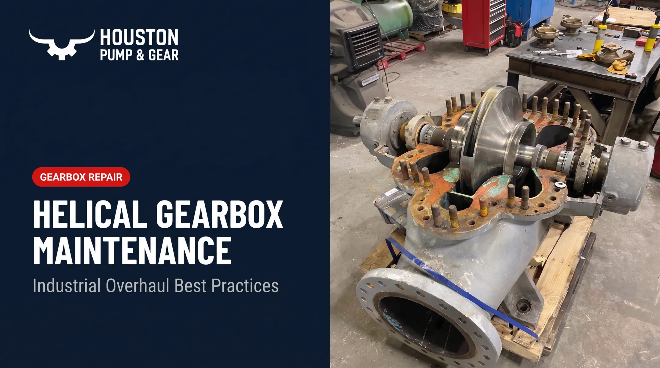
Helical reducers use angled teeth that mesh gradually, creating smoother contact than spur designs. Greater tooth contact area means quieter operation and higher load capacity.
Best suited for: continuous-duty, medium-to-heavy loads like conveyors and pumps.
- Strengths: smooth power transmission, durability under sustained operation, versatility
- Limitations: axial thrust that requires thrust bearings; slightly higher cost than spur types
In the field, helical platforms such as Falk Ultramite parallel shaft drives cover a wide duty range, with reduction ratios from 3.15:1 to 1200:1 and capacity from 0.25 to 100 hp.
Bevel Gear Reducers
Bevel reducers use cone-shaped gears on intersecting shafts, enabling right-angle power transmission instead of staying inline. That direction change, typically 90°, makes them useful where space is tight.
Best suited for: compact installations needing directional change, such as lifts and mixers.
- Strengths: space-saving layout, stable right-angle conversion
- Limitations: lower precision than parallel-axis designs; can demand more frequent maintenance under heavy loads
In cement processing and similar high-torque services, bevel and helical gearboxes show up often because they combine directional flexibility with strong load capacity—work Houston Pump & Gear regularly inspects and overhauls.

Worm Gear Reducers
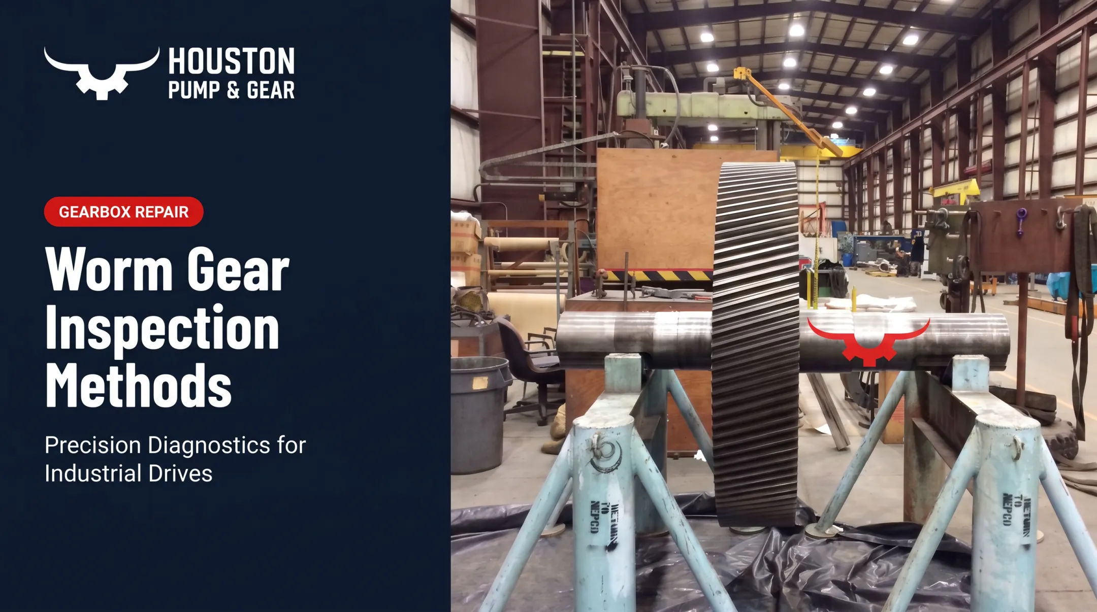
Worm reducers pair a worm shaft with a worm wheel at right angles, delivering high single-stage reduction ratios. Sliding contact, rather than rolling contact, enables self-locking, so the mechanism resists back-driving. No other gear type on this list does that inherently.
Best suited for: hoists, lifts, and intermittent-duty equipment needing back-drive prevention.
- Strengths: compact high-ratio reduction, quiet operation, inherent safety lock
- Limitations: lower transmission efficiency, prone to heat buildup under continuous heavy-duty use
That tradeoff shows up clearly on legacy industrial gearboxes. Heat-related wear is a common failure point on Lufkin worm and helical-worm units Houston Pump & Gear rebuilds, and worm-based designs such as Falk Hy-Power and UNI-Power 2000 helical-worm drives remain common in the field.
Planetary Gear Reducers
Planetary reducers use a coaxial layout (sun gear, planet gears, and ring gear) that spreads load across multiple contact points instead of a single gear path. Concentric input and output shafts also save axial space.
Best suited for: precision automation, robotics, and applications needing high torque density in compact space.
- Strengths: high efficiency, low backlash, long service life, excellent torque-to-size ratio
- Limitations: complex internals that need careful installation and proactive maintenance
A typical planetary unit has three or more planet gears rotating around a central sun gear. Depending on the configuration (shaft output, spindle output, or wheel drive), torque delivery can reach 332,000 N·m (about 245,000 lb-ft) on wheel-drive designs.

How to Choose the Right Type of Gear Reducer
The right type depends on load, precision, space, and operating conditions, not popularity or brand familiarity. Weigh these factors before specifying anything:
- Required torque and output speed for the driven equipment
- Duty cycle: continuous heavy-duty operation versus intermittent use
- Mounting orientation and installation space (top, wall, shaft, or flange mounting are common options)
- Precision and backlash tolerance the application demands
- Budget versus long-term maintenance and downtime costs
- Environmental exposure to dust, moisture, or temperature extremes
Mounting flexibility varies by brand and model, which matters when we're reconditioning a unit or matching a replacement to your existing footprint. Falk Ultramite gearboxes, for example, support top, wall, shaft, or flange mounting across their lineup, giving facilities more room to fit a reducer into tight or unconventional spaces. Our exchange program keeps spin-tested units on hand across these configurations, so a mounting mismatch doesn't turn into extended downtime.

What to Check Before Finalizing a Gear Reducer
Avoid over-specifying an advanced planetary unit when a simpler spur or helical design meets the need. Complexity adds cost and maintenance burden without adding value if the application doesn't require it. Don't ignore known tradeoffs either:
- Worm gears generate heat under sustained heavy loads
- Bevel gears lose precision in continuous heavy-duty service
- Planetary units require specialized installation know-how Long-term maintenance access matters just as much as the initial spec. Industrial facilities can't afford extended downtime, so selection guidance and fast emergency support carry real weight. Houston Pump & Gear's gearbox exchange program provides a refurbished, spin-tested unit matched to a customer's reduction ratio when there is no time to wait for a full repair. Base the final choice on documented application fit:
- Torque requirements
- Duty cycle
- Mounting constraints Familiarity with a particular brand or type is not enough on its own.
Conclusion
Gear reducers are essential for matching motor output to equipment needs across industrial and power generation applications. Spur, helical, bevel, worm, and planetary types each serve distinct needs based on load, precision, and space.
Understanding these differences, paired with reliable maintenance and repair support, leads to fewer failures and less costly downtime. Houston Pump & Gear has spent more than 20 years repairing and overhauling gearboxes across all five types, servicing major brands like Falk, Lufkin, and Horsburgh & Scott for industrial clients across Texas, Louisiana, and the broader U.S.
Frequently Asked Questions
What does a gear reducer do?
It lowers input rotational speed from a motor while increasing output torque, matching motor characteristics to the requirements of the driven equipment.
How do speed reducers work?
They use meshed gears of differing sizes so a smaller drive gear turns a larger driven gear more slowly, increasing torque in the process.
Does a gear reducer increase torque?
Yes. By design, as speed decreases through gear meshing, output torque increases proportionally.
How do I calculate the speed reduction ratio for a gearbox?
Divide the driven gear's tooth count by the drive gear's tooth count, or compare input RPM to output RPM. A 5:1 ratio means five input revolutions per output revolution.
What is the difference between a gearbox and a speed reducer?
A gearbox is a broader term covering speed increase, reduction, or direction change. A speed reducer specifically reduces speed and increases torque.
What is the purpose of a reduction gear in an electric vehicle?
It converts high motor RPM into usable wheel torque and speed, similar to its role in industrial motor-driven equipment — just on a smaller scale.