
Introduction
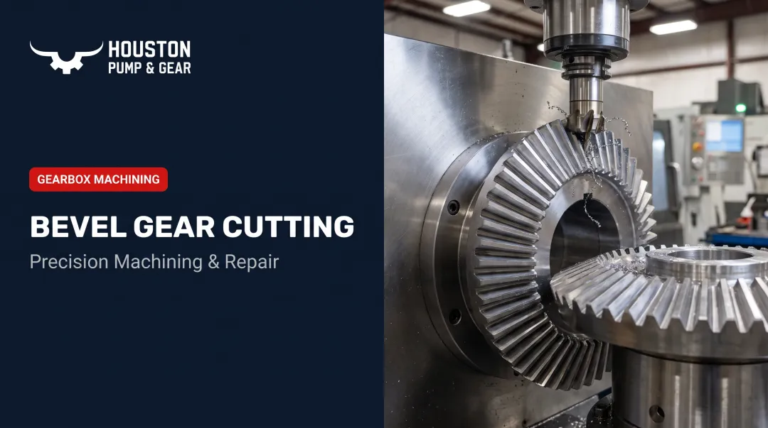
Spiral bevel gear cutting is the precision machining process that carves curved, angled teeth into cone-shaped gear blanks. It lets gears transmit power smoothly between shafts that intersect at an angle, usually 90 degrees.
If you manage maintenance at a power plant, spec gearboxes as an engineer, or buy machining services for heavy industry, this term shows up constantly in repair quotes and gearbox nameplates. Get the cutting geometry wrong, and you're dealing with excess noise, reduced load capacity, and a shortened equipment lifespan.
It still shows up in gearbox specs and failure reports, yet it's rarely explained in a way that helps with an actual repair-or-replace decision. This article covers what it is, why and where it's used, how the process works, what affects quality, and when re-cutting isn't the right fix.
Key Takeaways
- Spiral bevel gear cutting produces curved teeth for smooth, quiet power transfer between intersecting shafts
- Face milling (tapered tooth depth) and face hobbing (constant depth) are the two dominant cutting methods
- Blank material, cutter type, machine precision, and tooth accuracy requirements drive final gear quality
- Re-cutting a gear past its case-hardened depth can weaken it more than it helps
- Emergency gearbox failures often call for rapid assessment and remanufacture, not full on-site re-cutting
What Is Spiral Bevel Gear Cutting?
In spiral bevel gear cutting, a rotating cutter head machines curved tooth flanks into a cone-shaped blank so mating gears engage gradually along a spiral tooth line instead of all at once.
The goal is simple: gradual, continuous tooth contact between two shafts that intersect at an angle. That gradual engagement is what cuts down on noise and vibration while still transferring heavy torque loads reliably.
How it compares to other bevel gear types:
Straight bevel gears have teeth cut parallel to the cone's axis. They're cheaper and faster to cut, but they can't be ground after heat treatment and get noisy at higher speeds.
Hypoid gears look similar but run on offset, non-intersecting axes (think automotive rear differentials). Spiral bevel gears require intersecting axes; hypoid gears don't.
Within spiral bevel cutting itself, shops choose between two tooth-line geometries. Face milling produces a circular-arc tooth trace using single-index cutting, while face hobbing produces an extended-epicycloid trace using continuous-index cutting. Both are widely used; the choice depends on gear size, quantity, and finishing requirements. More on that in the next section.
There isn't a clean, universally agreed "two-brand" split between cutting systems the way some shop-floor talk suggests. The technically accurate distinction is circular-arc face milling versus extended-epicycloid face hobbing, and AGMA's own geometry standard for bevel and hypoid gears folds in multiple design-generation methods rather than just two.

Why Spiral Bevel Gear Cutting Is Used in Industrial and Power Transmission Applications
Industry leans on spiral bevel gearing for three reasons: high load capacity, smooth continuous tooth contact, and efficient power transfer between perpendicular shafts. Amarillo Gear, for example, reports 96%-98% calculated efficiency for its own spiral bevel sets, though actual efficiency varies with quality grade, ratio, and duty cycle.
Heavy industry demands equipment that runs quiet at high speed, holds up under continuous duty, and doesn't shake itself apart over years of operation. Spiral bevel geometry, when cut correctly, delivers all three. Straight-tooth alternatives simply can't compete once speeds climb.
What Happens Without Correct Geometry
Get the tooth geometry wrong (or let it degrade) and the consequences show up fast:
- Uneven wear across the tooth face
- Premature tooth failure, sometimes catastrophic
- Unplanned downtime that cascades through the whole facility
Downtime isn't cheap. ABB's 2023 survey of over 3,000 industrial maintenance decision-makers found unplanned outages cost a typical $125,000 per hour, and more than two-thirds of facilities experience one at least monthly.
That figure isn't specific to gearboxes, but a failed spiral bevel set inside a critical drivetrain will absolutely land you in that cost range.
Spiral bevel geometry follows established standards (AGMA/Gleason or Klingelnberg systems), not whatever a machinist feels like cutting that day. That same standards knowledge is what makes emergency response possible when a unit fails under load.
When Houston Pump & Gear got a call about a Lufkin S2212C gearbox that failed during an emergency shutdown at a power plant, the shop had to assess damage, source parts, or remanufacture components without delay. The team dispatched a truck the same day and pulled the unit.
They restored the plant to service within 72 hours. That timeline only works when a shop already knows spiral bevel geometry.
How Spiral Bevel Gear Cutting Works
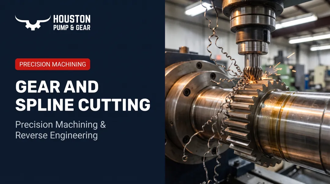
A cutter head and gear blank meet on a generating machine. The cutter rotates and indexes across the blank on a calculated path, forming both the concave and convex tooth flanks.
What goes into the process:
- A forged or cast alloy steel gear blank
- A cutter head with inside and outside blade sets
- Machine settings (tilt, swivel, and radial position) calculated from the target gear design
Modern shops control this through CNC multi-axis motion; older machines rely on mechanical cradle-style drivetrains. Either way, the shop also has to choose between the five-cut method and the completing method before the first chip comes off the blank.
Step 1: Machine Setup and Blank Preparation
The shop selects a cutter system, calculates tilt, swivel, and radial settings from the target tooth geometry, and mounts the blank on the generating machine. Get this step wrong and every downstream cut inherits the error.
Step 2: Cutting the Tooth Flanks
Two separate decisions drive the cut:
- Face milling vs. face hobbing: Face milling is single-index with tapered depth (deeper at the heel, shallower at the toe). Face hobbing is continuous-index with constant depth across the face — see Gear Technology's comparison.
- Five-cut vs. completing: Five-cut finishes gear and pinion flanks in five operations; completing cuts both pinion flanks in one pass from a solid blank. Face hobbing always uses completing; face milling can use either.
Step 3: Finishing and Verification
After cutting comes heat treatment, then lapping, skiving, or grinding based on the upstream method. Face-milled gears can usually be lapped, skived, or ground. Face-hobbed gears are typically lapped or skived; grinding is possible but not the preferred path.
Finished gears are checked on a coordinate measuring machine, then run through a rolling contact-pattern test. Thin marking compound goes on the teeth; the gears rotate together, and the transfer pattern is inspected to confirm proper mesh before the unit returns to service.

Where Spiral Bevel Gear Cutting Is Applied and What Affects the Process
Where It's Applied
Spiral bevel gears are used wherever power needs to change direction efficiently:
- Industrial gearboxes in power plants and pump drives
- Automotive differentials and axle systems
- Aerospace accessory drives, including helicopter rotor gearboxes
- Cooling tower and fan drive systems in heavy industry
Cutting itself typically happens once per gear set at original manufacture. Re-cutting or remanufacturing is episodic, done during major overhauls or after in-service failure rather than as routine maintenance.
Key Factors That Affect the Process
- Blank material and hardness: Carbon or alloy steel forgings affect tool wear, cycle time, and finish quality
- Cutter type and blade configuration: Face mill vs. face hob, carbide vs. high-speed steel, each influences achievable geometry and cycle speed
- Machine type and precision: Modern CNC multi-axis generators achieve tighter tolerance grades than older mechanical cradle machines
- Required tooth accuracy, pressure angle, and spiral angle: Dictated by the application's load, speed, and noise requirements
- Batch size and throughput: One-off MRO and repair jobs are handled differently than high-volume production runs
At Houston Pump & Gear, most of this work falls into the MRO category: custom-cutting replacement gears for in-service gearboxes, not production batches.
Common Issues, Misconceptions, and When Re-Cutting Isn't the Right Call
A few misconceptions cause real problems on the shop floor and in the field.
"Spiral bevel, straight bevel, and hypoid gears are interchangeable in setup." They're not. Each requires distinct machine settings, tooling, and cutters. Mixing them up doesn't just cost time. It produces a gear that won't mesh correctly with its mate.
"A worn gear can always be re-cut back to spec." Not always true. Once case-hardened tooth flanks wear past a certain depth, cutting into them removes the hardened layer entirely. That can leave a tooth weaker than before the repair, which is a worse outcome than the original wear.
"Correct cutting geometry guarantees good field performance." It doesn't. Mounting distance, backlash, and shaft alignment errors during installation can ruin tooth contact even on a perfectly cut gear. Shaft-angle error and axis error both shift the contact pattern regardless of how precisely the teeth were cut.
When Emergency Repair Beats On-Site Re-Cutting
During an emergency shutdown, full on-site spiral bevel re-cutting is usually impractical: there's no time, and the equipment isn't there. This is where mobile field response matters. Houston Pump & Gear's approach during emergencies combines 24/7 technician availability, same-day equipment pickup, and expedited shop evaluation rather than attempting a cut in the field:
- A technician assesses the failure and provides an on-the-spot read on severity.
- If removal is needed, a dedicated truck picks up the unit and transports it to the shop.
- Technicians disassemble, clean, and measure the gears, shafts, and housing to find the root cause.
- A detailed inspection report outlines the repair scope before any cutting begins.

That root-cause focus matters outside emergencies too. If a gear keeps failing despite correct geometry, the problem probably isn't the cut. Lubrication issues, misalignment, and overload cause repeat failures far more often than a bad tooth profile. Diagnose the root cause before ordering another re-cut. Otherwise you're just paying to repeat the same failure.
Frequently Asked Questions
What is the best angle for spiral gears?
The ideal spiral angle balances smoothness against thrust load, with 35 degrees commonly used as a standard reference point. The exact value still depends on shaft angle, tooth count, and the specific load requirements of your gear pair.
How do spiral bevel gears work?
Curved teeth engage gradually along the tooth face as the gears rotate around intersecting shafts. That gradual contact allows smoother torque transfer and noticeably less noise than straight bevel teeth.
What's the difference between face milling and face hobbing?
Face milling is single-index cutting that produces tapered tooth depth and usually needs a separate finishing pass. Face hobbing is continuous-index cutting that produces constant tooth depth, often with a different finishing path.
What's the difference between the five-cut and completing methods?
The five-cut method finishes the gear and pinion flanks across five separate operations. The completing method cuts both pinion flanks in a single operation from a solid blank.
What material is used to make spiral bevel gears?
Carbon or alloy steels, typically case-hardened, are standard for load-bearing industrial applications. Softer materials rarely hold up under the high-torque loads most spiral bevel gears see.
Can a damaged spiral bevel gear be repaired instead of replaced?
Minor wear or surface damage can sometimes be corrected through re-cutting or remanufacture. Severe tooth damage or hardened-layer loss usually means replacement. A shop that handles spiral bevel repair can tell you which option gets the unit back in service with less downtime.